Electric Underfloor Heating Systems for Milking Parlors on Dairy Farms
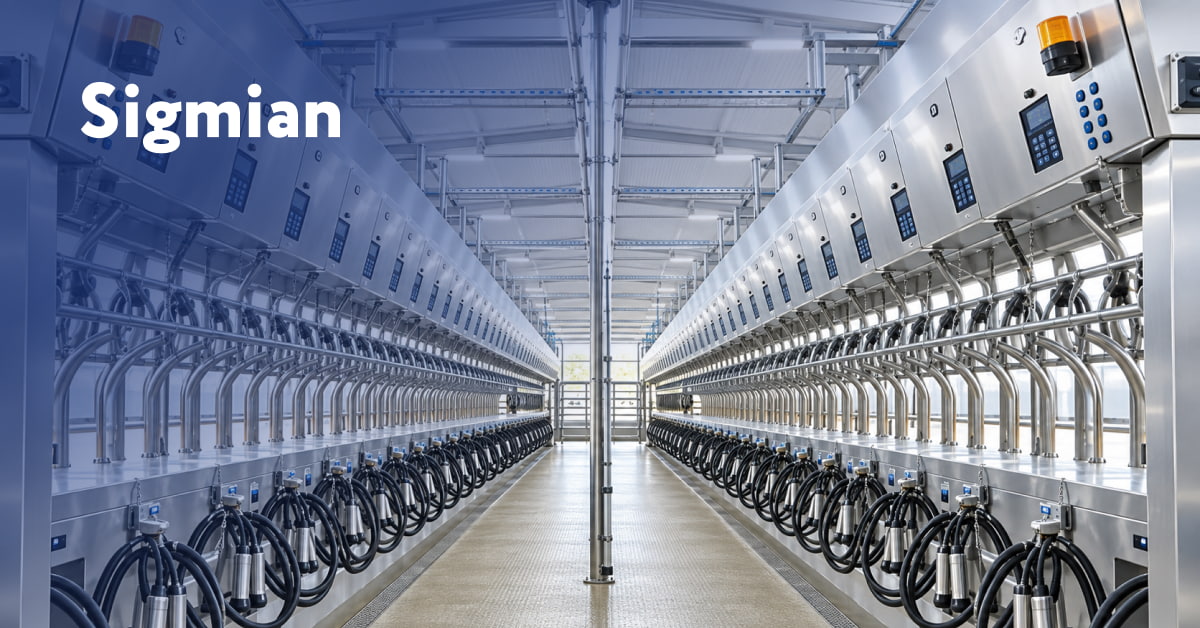
Fig. 1 — View of a milking parlor on a dairy farm
A modern milking parlor is a high-tech production facility equipped with electronic devices, among other systems. The milk produced is transported through hoses and pipelines. Milking itself is performed several times a day.
The use of an electric underfloor heating system in the milking parlors of dairy farms is essential for:
- creating a comfortable thermal regime for animals and machine milking operators;
- increasing milk yields and improving milk quality;
- ensuring rapid drying of the floor surface during cleaning of the milking parlor after the milking procedure;
- maintaining a constant, normal temperature for the stable operation of electronic equipment.
The electric underfloor heating system in a milking parlor differs substantially from a conventional electric underfloor heating system used in an urban apartment or a country house. The principal differences of the system under consideration are as follows:
- The specific heating power of this system is higher than that of a conventional electric underfloor heating system and ranges from 150 to 200 W/m².
- Heating cables are employed that are capable of long-term operation under conditions of high mechanical loads and elevated humidity, and that differ structurally from the cables used in residential electric underfloor heating systems.
- Owing to the structural characteristics of the pits in milking parlors, the installation of heating cables differs from that of a conventional electric underfloor heating system.
- When designing the heating system and selecting heating units, the limited options for supplying power to the heating units must be taken into account.
- The control subsystem employs a thermostat that maintains the specified surface temperature and operates according to a different algorithm than the controller used for a conventional electric underfloor heating system.
- Owing to the high specific power and the considerable heating area, a dedicated line of starting and protective apparatus — in the form of a control panel (CP) with all necessary automation — must be used to ensure the safety of the system.
- Since these systems are industrial electric heating systems, the heating units should be connected to the three phases of the power supply system in a sufficiently uniform manner.
Let us examine each of the above points in greater detail.
Specific Heating Power
Taking into account the need to heat the legs of personnel and to rapidly dry moisture, the target floor temperature in the milking area should be +20 to +22 °C. Since heat losses to the ground, heat transfer to the air, the energy consumed by moisture evaporation, and a reserve for rapid temperature recovery after the animals are brought in for milking must all be taken into account, the heating power should be no less than 150–200 W/m².
Type of Heating Cable Employed
To achieve the required specific heating power, single-core heating units of reinforced design — FrostResist, in the form of factory-manufactured products suitable for rapid installation — are employed. The units consist of a heating section and cold leads (cold lead length: 4 meters), connected by hermetically sealed couplings. Both ends are routed into a power junction box; the cable screen serves as the grounding element, which is necessary to ensure safety during operation of this electrical system. The entire unit assembly is already connected and factory-tested and requires no additional connections. However, the installation of the units must be performed in strict accordance with the design, observing the specified installation spacings and bending radii. Particular care should be taken to ensure that no air voids are present near the heating cable.
The 20FrostResist heating units are designed for an operating voltage of 220–240 V and have a linear power output of Plin. = 20 W/m, which allows them to be installed at a convenient installation spacing of H = 10 cm, thereby achieving a design specific heating power of Psp = 200 W/m².
For the characteristics of the 20FrostResist units, see Table 1.
| Heating unit type | Heating cable length, m | Operational power of heating unit, W |
|---|---|---|
| 20FrostResist-7-5 | 7 | 140 |
| 20FrostResist-12-5 | 12 | 240 |
| 20FrostResist-18-5 | 18 | 360 |
| 20FrostResist-25-5 | 25 | 500 |
| 20FrostResist-30-5 | 30 | 600 |
| 20FrostResist-40-5 | 40 | 800 |
| 20FrostResist-50-5 | 50 | 1000 |
| 20FrostResist-58-5 | 58 | 1160 |
| 20FrostResist-70-5 | 70 | 1400 |
| 20FrostResist-85-5 | 85 | 1700 |
| 20FrostResist-100-5 | 100 | 2000 |
| 20FrostResist-120-5 | 120 | 2400 |
| 20FrostResist-135-5 | 135 | 2700 |
| 20FrostResist-150-5 | 150 | 3000 |
| 20FrostResist-170-5 | 170 | 3400 |
| 20FrostResist-190-5 | 190 | 3800 |
Table 1. FrostResist single-core heating units (line with a specific power of 20 W/m)
Installation Details for Heating Units
The heating units are installed uniformly, without intersections, at a constant, fixed installation spacing of 10 cm across the entire heated area, along the entire length of the pit, and set back 7–10 cm from the edges of stairways and drainage channels.

Fig. 2 — Example of heating unit installation in the floor of a milking parlor.
Control Subsystem
The control subsystem is based on the PTM-2000 electronic thermostat with ambient air temperature sensors and heated floor surface temperature sensors.

Fig. 3 — PTM-2000 electronic controller and its temperature sensors.
The PTM-2000 temperature controller continuously monitors the ambient air temperature via the air temperature sensor. If the ambient temperature is within the established temperature range (from T1 min to T1 max), voltage is supplied to all power circuits. The temperature controller then begins to monitor the heated surface temperature via the second sensor — the surface temperature sensor. The PTM-2000 maintains the required heated surface temperature with a temperature hysteresis of ±2 °C. If the ambient temperature falls outside the established limits (below T1 min or above T1 max), all electrical circuits of the control panel are blocked and heating is switched off. The PTM-2000 thermostat is mounted on a standard DIN rail in the control panel, which contains, in addition to the controller:
- a residual current device (RCD);
- a system for switching heating operation between automatic and manual modes with corresponding indication;
- a system signaling heating activation, deactivation, and emergency shutdown.
All control panels are equipped with starting and protective automation from leading global manufacturers only — ABB, HAGER, MOELLER, etc.

Fig. 4 — Control panel composition